Introduction
You have seen that the reheat steam plant cycle, by staging the expansion, slightly improves the performance of the basic cycle.
The second area of improvement in power cycles consists in reducing irreversibility by temperature heterogeneity.
Let us examine the exchanges of the steam plant cycle with its external sources in order to determine where the most significant thermal irreversibilities are located.
On the cold source side, isothermal condensation makes it possible to limit the temperature difference between the working fluid and the cooling fluid, so that the irreversibilities by temperature heterogeneity are low.
On the side of the hot source, on the other hand, a fuel is burned in the boiler capable of producing fumes at more than 2000 °C to heat the working fluid to much lower temperatures: in the economizer the water comes out of the pumps at a few tens of degrees Celsius, while vaporization and reheat take place at several hundred degrees C.
In all cases the temperature differences with the hot source are very high, but it is clearly in the economizer that is found the greatest irreversibility by temperature heterogeneity. It is therefore at this level that we will seek to improve the cycle
Regenerative reheat cycle

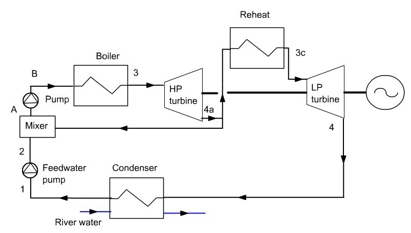
Consider a cycle with reheat. If we extract a little quantity of steam, called bleed steam, at the outlet of the first expansion, at point 4a in the figure, its pressure remains sufficient to be able to condense it at a temperature high enough to preheat the pressurized water leaving the pump in point 2 in a mixer called an open feedwater heater.
The enthalpy of the vapor being very much higher than that of the liquid, due to the latent heat of vaporization, it is conceivable that it is possible to ensure the preheating of the liquid thanks to a small extraction of bleed steam during expansion.
Of course, for the operation to be possible, the steam withdrawn must be at a temperature higher than that of the liquid, which means that in practice, we must limit ourselves to partial water preheating.
Note that, when there is a bleed extraction, the mass flow rate of the fluid which evolves is not the same in the different parts of the machine. If ε is the bleed steam rate, and for a unit mass flow, the fluid flow between points 4a, 3c, 4, 1 and 2 is equal to (1 - ε), and that which evolves between points A, 3a, 3b, 3 and 4a is equal to 1.
Overall, extractions may contribute to an improvement of almost five points of the internal efficiency of the Rankine cycle. Combined with reheat, the gain is about 7 percentage points, a 20% higher efficiency than the basic cycle.
In practice, in high-capacity power plants used in electricity generation, several extractions are used (from 6 to 9), the various feedwater heaters operating at temperatures ranging from 30 to 50 °C
There are two kinds of feedwater heaters:
- open feedwater heaters in which the hot fluid (the extracted steam) and the cold fluid (the condensed water) are mixed;
- closed feedwater heaters in which the heat transfer between the two fluids takes place in a conventional exchanger. The condensed steam leaving the exchanger is then expanded to the condensing pressure and mixed with the steam leaving the LP turbine before entering the condenser.
In the first case, it is necessary to provide two pumps in the water circuit, while in the second, one is enough but you must install heat exchangers.
Loading the model
Loading the model of the regenerative reheat cycle
Click on the following link: Open a file in Thermoptim
You can also:
- either open the "Project files/Example catalog" (CtrlE) and select model m8.2 in Chapter 8 model list.
- or directly open the diagram file (steamExtrReheat.dia) using the "File / Open" menu in the diagram editor menu, and the project file (steamExtrReheat.prj) using the "Project files/Load a project" menu from the simulator.
Cycle plot in the water (h, ln(P)) chart
First step: loading the water (h, ln(P)) chart
Click this button
You can also open the chart using the "Interactive Charts" line in the "Special" menu of the simulator screen, which opens an interface that links the simulator and the charts. Double-click in the field at the top left of this interface to choose the type of chart desired (here "Vapors").
Once the chart is open, choose "water" from the Substance menu, and select "(h, p)" from the "Chart" menu.
Second step: loading the reference cycle and the cycle with reheat and extraction
Click this button
You can also open this cycle in the following way: in the chart window, choose "Load a cycle" from the Cycle menu, and select "cycle_RefEnThin.txt" puis "cycle_ExtrReheatEnThin.txt" in the list of available cycles.
You get the plot of the cycles in the (h, ln (P)) chart: the new cycle in black and the refernce cycle in blue.
The interpretation of the diagram is more difficult than before, since the flow rate varies according to the processes.
Steam extraction modeling
 To
correctly model the extraction in Thermoptim, you need to use a
divider and a mixer, which are nodes. These nodes make it possible to
model the elements of the diagram where the mixtures and the divisions
of fluids take place.
In a node, several junctions of fluid represented by processes are connected to form a single vein.
A node screen is roughly divided in three parts
- at the top, the name of the node and its type, as well as its main branch are indicated
- below appear branches
- on the right are placed the buttons allowing to build and calculate the node
Note that the state of a mixer outlet point is generally different from that of the inlet points, while in a divider, the state is the same for inlet and outlet. It is therefore necessary that the upstream point of the outlet process of a mixer be different from the downstream points of its branches, while the same point should appear upstream and downstream of a divider.
Setting mixers and dividers
The setting of a mixer does not pose any particular problem: when you click on the "Calculate" button, Thermoptim performs mass and enthalpy balances of the branches and calculates the outlet temperature, and the inlet point of the downstream process is recalculated.
Setting up a divider is a little more complex. The screen of a divider has an additional button called "flow setting". It is used to define flow factors which are used when calculating the distribution of flow between the branches. The basic idea is as follows: since a divider must ensure the conservation of the flow, it is not always possible to set the values of the flow rates of the branches when that of the main vein varies.
We therefore ask the user to define a flow factor which represents the share of the total flow which passes through the branch considered.
Thermoptim sums up all the flow factors of the different branches, then distributes the total flow proportionally to these.
An exception exists however: it is possible to set the flow in a process at the outlet of a divider, provided that this divider has only two branches: that with set flow and another.
In this case, the flow of the second process is calculated as equal to the flow in the main vein minus that of the branch where it is set, and the flow factors of the two branches are recalculated to correspond to this distribution.
In this case a "set flow" label is displayed in red below the name of the main vein.
Divider study
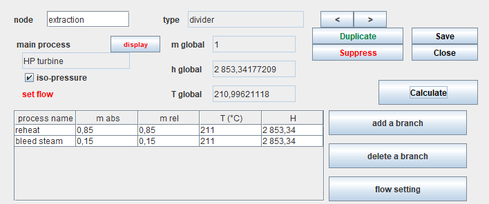
Open the divider screen in the model. The main vein is the HP turbine, and the two branches are extraction and reheat. Their respective flow rates are 0.15 kg/s and 0.85 kg/s.
Click on Calculate. The text "set flow" appears in red, indicating that one of the two outlet processes is set in this way. You can verify that this is the extraction process-point.
The flow in each of the branches is updated.
Mixer study
Open the mixer screen in the model. The two branches are the extraction and the extraction pump, and the main vein is the feedwater pump. Their respective flow rates are 0.15 kg/s and 0.85 kg/s. You can check that the state of the two upstream points is different, so that you need a third point at the entrance of the main vein.
No particular setting is necessary, Thermoptim having all the information to calculate the node.
Click on Calculate. The state of the outlet point of the mixer is determined, as well as the flow rate of the process.
Balance of the regenerative reheat cycle
With an extraction flow of 15% of the main flow and an intermediate pressure of 10 bar, the result of the modeling of the regenerative reheat cycle is provided by Thermoptim: the efficiency increases from 41.9% for the reheat cycle to 43.2% for the new one.
First law balance
What is the value of the useful power?
What is the value of the purchased power?
Reduction in useful power
By what value does the useful power decrease?
By what value does purchased power decrease?
Parametric study of the regenerative reheat cycle
Exercise: find the maximum extraction flow.
Increase the extraction rate to the possible limit, which corresponds to the case where the state of the fluid leaving the mixer (point A) becomes two-phase, by studying its influence on cycle performance (efficiency and power).
Beyond this limit, compression in the "feed pump" process can no longer be carried out in the liquid state, and Thermoptim displays a message.
To change the value of the flow, open the screen of the "extraction" process, modify its flow and click on "Calculate". Then recalculate the whole project several times in the simulator screen until the balance stabilizes.
Conclusion
This exploration allowed you to see the interest of the steam bleed extraction on the performance of the plant.
It also showed you how to set dividers.
The effect of the bleed steam extraction is to reduce the useful power compared to the reheat cycle. This is due to the reduction in the flow rate which passes through the low pressure turbine.
For comparison, this synoptic view provides you with the performance values of the reheat plant.